Decision Procedure for Originating Numbers in SMS over NAS
Previous articles 1 and 2 clarified the decision procedure for originating numbers in short message service (SMS) via the Mobile Switching Centre (MSC) and over the IP Multimedia Subsystem (IMS). However, SMS in 5G mobile networks may also be provided over the Non-Access Stratum (NAS) protocol. By analyzing packets and logs generated when sending and receiving a short message in a private 5G mobile network, this article clarifies how originating numbers are determined in SMS over NAS.
Summary
The originating numbers in SMS over NAS may be determined based on the sender’s Generic Public Subscription Identifier (GPSI). In SMS over NAS in 5G Core (5GC), SMS Protocol Data Units (PDUs) are forwarded to the Short Message Service Center (SMSC) via the Short Message Service Function (SMSF). The user equipment (UE) submits the GPSI assigned to it when using SMSF services. The GPSI can include the Mobile Subscriber ISDN Number (MSISDN), that is, the phone number assigned to the UE. The SMSF provides the SMSC with the sender’s phone number retrieved from the GPSI, enabling the SMSC to determine the originating number.
Introduction to SMS over NAS
SMS over NAS transfers short messages using the NAS protocol, which provides direct communication between the UE and core network. Mobile networks have a Radio Access Network (RAN) between the UE and core network, where base stations physically connect them using wireless communication technology. NAS is a protocol to virtually connect the UE and core network without being dependent on the communication technology used in the RAN. SMS over NAS, which encapsulates and forwards SMS PDUs in this protocol, is supported by 5GC along with SMS over IMS.
SMS over NAS in 5GC is provided by the SMSF. The SMSF is specified as one of the Network Functions (NFs) in 3GPP TS 23.501¹, which defines the 5G system architecture. It supports the functions required for short message transfer between the UE and SMSC. Figure 1 shows the architecture of the NFs supporting SMS over NAS, based on Section 4.4.2 of TS 23.501. In the figure, the Access and Mobility Management Function (AMF) is the NF that serves as the point of contact with the UE. It also relays short messages forwarded between the UE and SMSF. The Unified Data Management (UDM) is the NF that provides the subscriber information necessary for relaying these messages. The SMSF forwards short messages to the SMSC through a gateway or router.
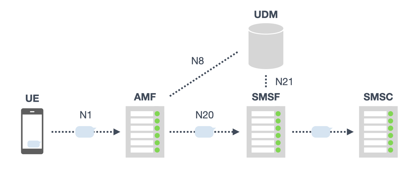
For SMS over NAS in 5GC, SMS PDUs are encapsulated in NAS only between the UE and AMF. 3GPP TS 29.500², which defines the 5G service architecture, specifies that NF-to-NF communication is performed using the Hypertext Transfer Protocol Version 2 (HTTP/2). The services of each NF are provided via Application Program Interfaces (APIs), which are accessed using HTTP/2. In Figure 1, the N1 interface uses NAS, and the other Nx interfaces use HTTP/2. Therefore, SMS PDUs are encapsulated in NAS between the UE and AMF, and in HTTP/2 between the AMF and SMSF.
Identification of the Sender
The procedures for short message transfer in SMS over NAS are presented in 3GPP TS 23.502³, which defines the 5G system procedures. Figure 2 shows the sequence of short message submission in SMS over NAS, based on Section 4.13.3.3 of TS 23.502. The SMS-SUBMIT sent from the UE is encapsulated in the Uplink NAS transport message and arrives at the AMF (Step 1 in Figure 2). It is then encapsulated in HTTP/2 by AMF, sent to SMSF by the Nsmsf_SMService_UplinkSMS service request, and subsequently forwarded to the SMSC (Steps 2 and 3 in Figure 2). Then, a message is forwarded to the UE, notifying that the SMS-SUBMIT was successfully received by the SMSC (Steps 4 and 5 in Figure 2).

When requesting the Nsmsf_SMService_UplinkSMS service from the SMSF, AMF submits the service user’s details along with the SMS-SUBMIT. The usage of this service is described in 3GPP TS 29.540⁴, which defines the SMSF specifications. According to TS 29.540, an HTTP/2 request to this service loads SmsRecordData in addition to SMS-SUBMIT. SmsRecordData is data in JavaScript Object Notation (JSON) format for invoking this service. Figure 3 shows the HTTP/2 request, as exemplified in Section B.3 of TS 29.540. The upper part of the request body contains a phone number in the gpsi element of SmsRecordData. The value of this element is the GPSI of the service user. As defined in 3GPP TS 29.571⁵, the GPSI may include MSISDN; therefore, the originating number of the short message may be determined based on this value.
POST /example.com/nsmsf-sms/v1/ue-contexts/{supi}/sendsms HTTP/2
Content-Type: multipart/related; boundary=----Boundary
Content-Length: xyz

------Boundary
Content-Type: application/json

{
    "smsRecordId": "777c3edf-129f-486e-a3f8-c48e7b515605",
    "smsPayload": {
        "contentId": "sms"
        },
    "gpsi": "msisdn-8613915900000",
    "pei": "imei-123456789012345",
    "accessType": "3GPP_ACCESS",
    "ueLocation": {
        "nrLocation": {
            "tai": {
                "plmnId": {
                    "mcc": "46",
                    "mnc": "000"
                },
                "tac": "A01001"
            },
            "ncgi": {
                "plmnId": {
                    "mcc": "46",
                    "mnc": "000"
                },
                "nrCellId": "225BD6007"
            }
        }
    },
    "ueTimeZone": "+08:00"
}
------Boundary
Content-Type: application/vnd.3gpp.sms
Content-Id: sms

{ ... SMS Message binary data ...}
------Boundary
Moreover, the AMF submits the service user’s details before requesting the Nsmsf_SMService_UplinkSMS service from the SMSF. In order for a UE to use SMSF services, it must be activated by the SMSF via the Nsmsf_SMService_Activate service. TS 23.502 describes that an HTTP/2 request to this service may include GPSI.
The AMF invokes Nsmsf_SMService_Activate service operation from the SMSF. The invocation includes AMF address, Access Type, RAT Type, Trace Requirements, GPSI (if available) and SUPI.
Additionally, according to TS 29.540, the body of an HTTP/2 request to this service is loaded with UeSmsContextData, and this data in JSON format may include the gpsi element. As mentioned earlier, GPSI may include MSISDN, thus the SMSF may be able to identify the UE’s phone number before short message transfer.
Reproduction of Short Message Transfer
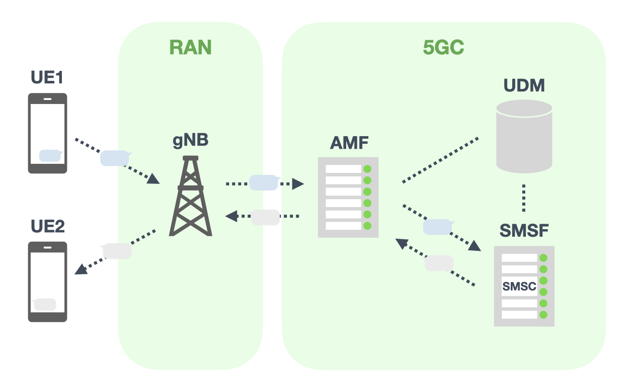
To clarify the decision procedure for originating numbers in SMS over NAS, a private 5G mobile network was built to reproduce short message transfers. The mobile network was built using Open5GS⁶ as 5GC and srsRAN⁷ as RAN. Figure 4 shows the deployed mobile network. The latest version of Open5GS at the time of writing, v2.7.2, does not implement SMSF. However, a pull request implementing SMSF (hereafter referred to as “pr_SMSF”) has been proposed by jmasterfunk84⁸. This pull request includes certain functions of an SMSC. Therefore, SMS over NAS can be implemented by merging pr_SMSF into Open5GS.
Short message transfer over NAS was reproduced in a shielded box. Figure 5 shows the devices used in the demonstration. The USRP B205mini-i⁹ was used as the radio hardware for the gNB (Next Generation Node B), with the Galaxy S24 serving as UE1 and the Pixel 6 as UE2. These devices were combined into the USB hub and connected to a MacBook Pro outside the box. Open5GS with pr_SMSF merged and srsRAN were run on Ubuntu running on VMware on the MacBook Pro. The subscriber information as described in the previous article was reused for this demonstration; therefore, UE1 was assigned the phone number 818001234567, while UE2 was assigned 819001234567.
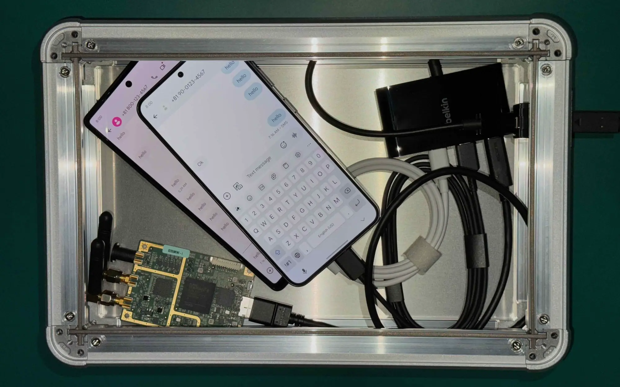
Figure 6 shows the demonstration of short message transfer over NAS. In the figure, UEs are operated via scrcpy, and UE1 (right) sends a short message to UE2 (left). On the screen of UE1, the phone number 819001234567 of UE2 is displayed as the destination number of the message. On the screen of UE2, which received the message, the phone number 818001234567 of UE1 is displayed as the originating number. By analyzing the packets and logs generated during the demonstration, the decision procedure for the originating number can be clarified.
Clarification of the Decision Procedure
To clarify the decision procedure for the originating number in SMS over NAS, the packets captured in the mobile network and the logs generated by the SMSF were analyzed. First, based on the packets captured when UE1 attaches to the mobile network, the procedure for AMF to retrieve UE1’s phone number and for AMF to activate UE1’s SMS are reviewed. Next, based on the packets generated when UE1 sends a short message to UE2, the procedure for AMF and SMSF to forward the short message are reviewed. Finally, by reviewing the processing of the SMSC functions included in the SMSF, the decision procedure for the originating number is clarified.
Preprocess for SMSF Services
When the UE attaches to the mobile network, the AMF retrieves UE’s phone number based on its Subscription Permanent Identifier (SUPI) and then activates the SMS for UE. SUPI is the identifier of the subscriber in a 5G mobile network and serves as the traditional International Mobile Subscriber Identity (IMSI). Figure 7 shows the associated HTTP/2 packets when UE1 attaches to the mobile network, and Figure 8 shows the sequence. The AMF retrieves subscriber information, including MSISDN, from the UDM based on the SUPI written on the SIM card inserted in UE1 (Steps 1 and 2 in Figure 8). Then, the AMF activates SMS for UE1 by submitting the retrieved subscriber information to the SMSF (Step 3 in Figure 8).

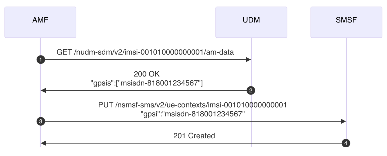
To use SMS, the UE must activate it by submitting its subscriber information to the SMSF. For this purpose, the AMF retrieves subscriber information from the UDM when the UE attaches to the mobile network. Specifically, the AMF requests the Nudm_SubscriberDataManagement service of the UDM to retrieve information tied to the UE’s SUPI. Figure 9 shows the HTTP/2 communication when the AMF uses this service to retrieve UE1’s MSISDN. The request path includes UE1’s SUPI, and the gpsis element of the response body includes the MSISDN associated with it. As a result, the AMF recognizes UE1’s phone number as 818001234567.
:method: GET
:path: /nudm-sdm/v2/imsi-001010000000001/am-data
:scheme: http
:authority: 127.0.0.12:7777
accept: application/json,application/problem+json
3gpp-sbi-sender-timestamp: Sat, 05 Oct 2024 07:15:55.265 GMT
3gpp-sbi-max-rsp-time: 10000
user-agent: AMF
:status: 200
server: Open5GS v2.4.8-709-g860c50b
date: Sat, 05 Oct 2024 07:15:55 GMT
content-length: 148
content-type: application/json

{
    "gpsis": [
        "msisdn-818001234567"
    ],
    "subscribedUeAmbr": {
        "uplink": "1000000 Kbps",
        "downlink": "1000000 Kbps"
    },
    "nssai": {
        "defaultSingleNssais": [
            {
                "sst": 1
            }
        ]
    }
}
Upon retrieving the subscriber information, the AMF submits it to the SMSF to activate SMS for UE. Specifically, the AMF submits the UE’s subscriber information to the Nsmsf_SMService_Activate service of the SMSF. Figure 10 shows the HTTP/2 communication when the AMF uses this service to activate SMS for UE1. UE1’s SUPI in the request path and its MSISDN in the gpsi element of the request body are submitted together to the SMSF. As a result, the SMSF recognizes UE1’s phone number as 818001234567.
:method: PUT
:path: /nsmsf-sms/v2/ue-contexts/imsi-001010000000001
:scheme: http
:authority: 127.0.0.21:7777
content-type: application/json
user-agent: AMF
accept: application/json,application/problem+json
3gpp-sbi-sender-timestamp: Sat, 05 Oct 2024 07:15:55.281 GMT
3gpp-sbi-max-rsp-time: 10000
content-length: 361

{
    "supi": "imsi-001010000000001",
    "amfId": "7ecb2f10-82e9-41ef-a591-c3e912b59599",
    "accessType": "3GPP_ACCESS",
    "gpsi": "msisdn-818001234567",
    "ueLocation": {
        "nrLocation": {
            "tai": {
                "plmnId": {
                    "mcc": "001",
                    "mnc": "01"
                },
                "tac": "000007"
            },
            "ncgi": {
                "plmnId": {
                    "mcc": "001",
                    "mnc": "01"
                },
                "nrCellId": "00066c000"
            },
            "ueLocationTimestamp": "2024-10-05T07:15:55.122425Z"
        }
    },
    "ueTimeZone": "+00:00"
}
:status: 201
server: Open5GS v2.4.8-709-g860c50b
date: Sat, 05 Oct 2024 07:15:55 GMT
content-length: 105
location: http://127.0.0.21:7777/nsmsf-sms/v2/ue-contexts/imsi-001010000000001
content-type: application/json

{
    "supi": "imsi-001010000000001",
    "amfId": "7ecb2f10-82e9-41ef-a591-c3e912b59599",
    "accessType": "3GPP_ACCESS"
}
Transfer of a Short Message
Once SMS is activated, the UE sends short messages over NAS. Figure 11 shows the associated NAS and HTTP/2 packets when UE1 sends a short message to UE2. In Figure 11, the source of the HTTP/2 request is 127.0.0.1 due to the Open5GS implementation¹⁰. Figure 12 shows the sequence of packets in Figure 11. The HTTP/2 request body to the Nsmsf_SMService_UplinkSMS service in Step 2 of Figure 12 may contain UE1’s GPSI as exemplified in Figure 3.

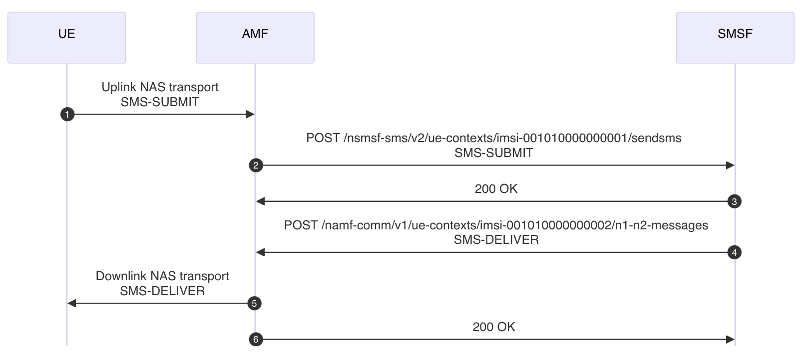
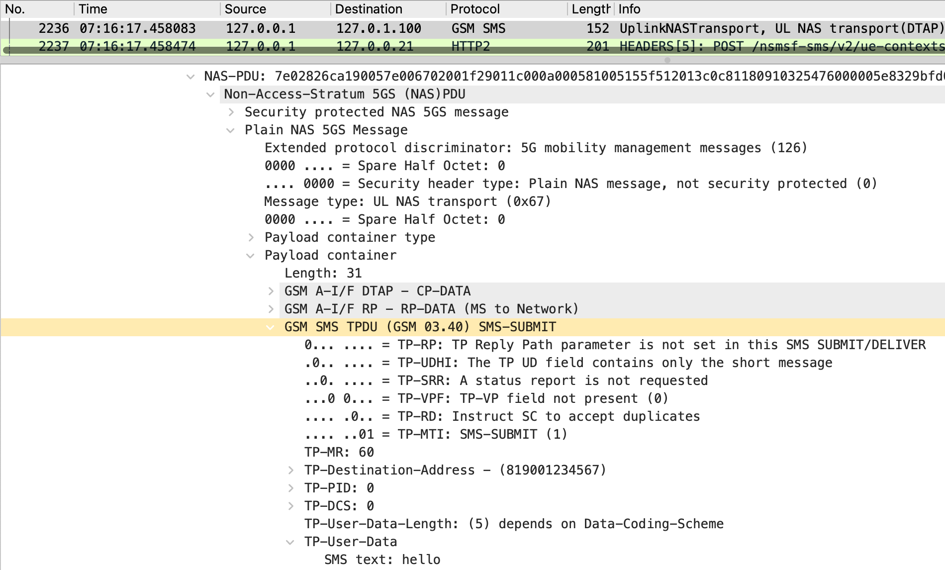
Contrary to the example shown in Figure 3, the service user’s GPSI is not included in the HTTP/2 request to the Nsmsf_SMService_UplinkSMS service. Figure 13 shows the Uplink NAS transport message in Step 1 of Figure 12, and Figure 14 shows the HTTP/2 request to the Nsmsf_SMService_UplinkSMS service in Step 2. As shown in Figure 13, the SMS-SUBMIT forwarded from UE1 to AMF is loaded into the PDU of the Uplink NAS transport message. In contrast, as shown in Figure 14, the SMS-SUBMIT forwarded from AMF to SMSF is loaded into the lower part of the request body, which is the part whose content type is application/vnd.3gpp.sms. However, the gpsi element is not included in the SmsRecordData loaded in the upper part. Therefore, this request does not contain UE1’s phone number, which is the originating number of the short message.
:method: POST
:path: /nsmsf-sms/v2/ue-contexts/imsi-001010000000001/sendsms
:scheme: http
:authority: 127.0.0.21:7777
accept: application/json,application/problem+json
3gpp-sbi-sender-timestamp: Sat, 05 Oct 2024 07:16:17.458 GMT
3gpp-sbi-max-rsp-time: 10000
content-type: multipart/related; boundary="=-fDIN7NO9ft2yVyD2Y+1kFg=="
user-agent: AMF
content-length: 499

--=-fDIN7NO9ft2yVyD2Y+1kFg==
Content-Type: application/json

{
    "smsRecordId": "1",
    "smsPayload": {
        "contentId": "sms"
    },
    "ueLocation": {
        "nrLocation": {
            "tai": {
                "plmnId": {
                    "mcc": "001",
                    "mnc": "01"
                },
                "tac": "000007"
            },
            "ncgi": {
                "plmnId": {
                    "mcc": "001",
                    "mnc": "01"
                },
                "nrCellId": "00066c000"
            },
            "ueLocationTimestamp": "2024-10-05T07:15:55.122425Z"
        }
    },
    "ueTimeZone": "+00:00"
}
--=-fDIN7NO9ft2yVyD2Y+1kFg==
Content-Id: sms
Content-Type: application/vnd.3gpp.sms

).......QU...<...    .2Tv....2...
--=-fDIN7NO9ft2yVyD2Y+1kFg==--
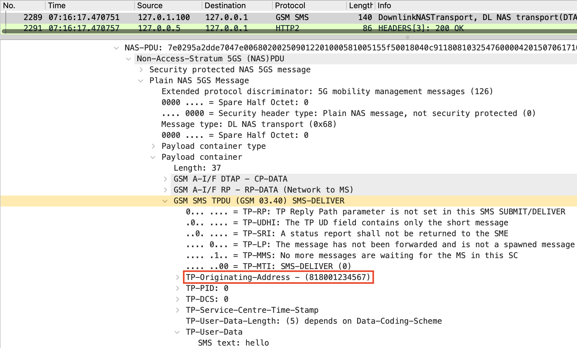
The SMSC determines the originating number of the short message through a process and loads it into the SMS-DELIVER. Figure 15 shows the HTTP/2 request to the Namf_Communication_N1N2MessageTransfer service in Step 4 of Figure 12, and Figure 16 shows the Downlink NAS transport message in Step 5. As shown in Figure 15, the SMS-DELIVER forwarded from SMSF to AMF is loaded into the lower part of the request body. In contrast, as shown in Figure 16, the SMS-DELIVER forwarded from AMF to UE1 is loaded into the PDU of the Downlink NAS transport message. The TP-Originating-Address (TP-OA) field of the SMS-DELIVER is loaded with UE1’s phone number 818001234567, the originating number. To clarify how the value of the TP-OA field is determined, the processing of the SMSC functions is to be reviewed.
:method: POST
:path: /namf-comm/v1/ue-contexts/imsi-001010000000002/n1-n2-messages
:scheme: http
:authority: 127.0.0.5:7777
user-agent: SMSF
accept: application/json,application/problem+json
3gpp-sbi-sender-timestamp: Sat, 05 Oct 2024 07:16:17.460 GMT
3gpp-sbi-max-rsp-time: 10000
content-type: multipart/related; boundary="=-1T0SbhcFR02+SKFtM3uBZQ=="
content-length: 314

--=-1T0SbhcFR02+SKFtM3uBZQ==
Content-Type: application/json

{
    "n1MessageContainer": {
        "n1MessageClass": "SMS",
        "n1MessageContent": {
            "contentId": "sms"
        }
    }
}
--=-1T0SbhcFR02+SKFtM3uBZQ==
Content-Id: sms
Content-Type: application/vnd.3gpp.5gnas

    .".....QU.........2Tv..B.Ppaq...2...
--=-1T0SbhcFR02+SKFtM3uBZQ==--
Decision Procedure at SMSC
Based on the logs generated by the SMSF during the short message transfer, the SMSC functions are analyzed. Figure 17 shows the debug log of the SMSF when it receives the SMS-SUBMIT. This log shows that after the request for the Nsmsf_SMService_UplinkSMS service is handled in smsf/nsmsf_handler.c, the SMS-SUBMIT is processed in smsf/sms.c. According to the implementation in smsf/nsmsf_handler.c, this log is generated by the smsf_nsmsf_sm_service_handle_uplink_sms(). Figure 18 shows the code and comments included in this function¹¹. From this, it is inferred that the smsf_send_to_internal_smsc() implemented in smsf/sms.c provides the SMSC functions.

/* The SMSF normally sends the RP-DATA payload to the SMSC here.
* For future work, this can use either Diameter SGd, MAP, or SBI.
* We will process the message here to allow for local delivery.
*/
memset(¶m, 0, sizeof(param));
ogs_pkbuf_t *smsc_result;
smsc_result = smsf_send_to_internal_smsc(smsf_ue, stream, sms_payload_buf);
if (smsc_result) {
param.n1smbuf = smsf_sms_encode_cp_data(ti_flag_ack,
cp_header->flags.tio, smsc_result);
ogs_assert(param.n1smbuf);
smsf_namf_comm_send_n1_n2_message_transfer(
smsf_ue, stream, ¶m);
}
The SMSC functions implemented in pr_SMSF identify the originating number from the sender’s GPSI. In the smsf_send_to_internal_smsc(), after confirming the existence of the destination specified in the SMS-SUBMIT, the smsf_copy_submit_to_deliver() constructs the SMS-DELIVER. In this function, the code shown in Figure 19 determines the TP-OA field of the SMS-DELIVER¹². This code retrieves the value of the oa_msisdn variable to be loaded into the TP-OA field by ogs_id_get_value(smsf_ue->gpsi). This means that if the GPSI is msisdn-818001234567, then 818001234567 will be extracted. Thus, the phone number contained in the GPSI submitted by the sender to the Nsmsf_SMService_Activate service is determined as the originating number.
/* Populate the Sender's MSISDN */
char *oa_msisdn;
if (strncmp(smsf_ue->gpsi, OGS_ID_GPSI_TYPE_MSISDN,
        strlen(OGS_ID_GPSI_TYPE_MSISDN)) == 0) {
    oa_msisdn = ogs_id_get_value(smsf_ue->gpsi);
    ogs_assert(oa_msisdn);
} else {
    ogs_error("SMS-MO without MSISDN");
}
Conclusion and Future Work
For SMS over NAS in 5GC, the originating numbers of short messages may be determined based on the sender’s GPSI. The SMSF and SMSC functions used in this test extracted the originating number from the GPSI submitted by the sender. However, this answer is derived from testing unofficial pr_SMSF on a private 5G mobile network. In the future, it will be important to focus on the process of pr_SMSF being officially merged into Open5GS. Moreover, when other open-source 5GCs implement SMSF, it will be necessary to test them.
¹ 3GPP TS 23.501, System architecture for the 5G System (5GS)
² 3GPP TS 29.500, 5G System; Technical Realization of Service Based Architecture; Stage 3
³ 3GPP TS 23.502, Procedures for the 5G System (5GS)
⁴ 3GPP TS 29.540, 5G System; SMS Services; Stage 3
⁵ 3GPP TS 29.571, 5G System; Common Data Types for Service Based Interfaces; Stage 3
⁶ Open5GS - Open Source implementation for 5G Core and EPC
⁷ srsRAN Project - Open Source RAN
⁸ [SMSF] Introduce Short Message Service Function #2938 · open5gs/open5gs - GitHub
⁹ USRP B205mini-i (Board Only) - Ettus Research, a National Instruments Brand
¹⁰ SBI message source IP bound to 127.0.0.1 #3339 · open5gs/open5gs - GitHub
¹¹ jmasterfunk84/open5gs/src/smsf/nsmsf-handler.c#L199-L212 - GitHub
¹² jmasterfunk84/open5gs/src/smsf/sms.c#L228-L236 - GitHub